
Solar Simulators
Full-LED, Xenon, LED-hybrid and steady-state systems for IEC 60904-9 measurement.
 Electroluminescence Imaging
Perovskite and tandem
Perovskite tandem testing
Hold the device in its stabilised state. Give each junction its own light.
A perovskite-silicon tandem is two problems at once. The perovskite moves with its light and bias history, and the tandem is limited by whichever junction gets less of its light. A Nexun PRO or PRO Max with the steady-state add-on handles both: it preconditions the device under continuous light, tunes its LED bands until each junction gets the current it would get under AM1.5G, then measures.
Why tandems are hard
A moving device under the wrong light gives the wrong number
Silicon cells give the same I‑V curve whenever you flash them. Perovskites and tandems do not, for two reasons that add up.
Metastability
Ions move inside the perovskite under light and voltage. The cell you measure depends on the seconds to minutes before the sweep: measured cold it under-reads, swept too fast it shows hysteresis between forward and reverse.
Current matching
In a two-terminal tandem the same current flows through both junctions, so the weaker one sets it. If the simulator gives the top cell slightly more light than AM1.5G and the bottom cell slightly less, the wrong junction limits and the efficiency and fill factor shift.
Spectral mismatch is not a single factor
For a single-junction cell one mismatch factor corrects the current. For a tandem it cannot: each junction has its own mismatch, and the limiting one can change. The spectrum has to be right per junction before the measurement, not corrected after it.
The method
Five steps from a moving device to a defensible number
The same sequence for cells and full-size modules, with every step logged with the result.
- Measure the spectral response of each junctionEQE of the top and bottom cell, with light and voltage bias to isolate one junction at a time (IEC 60904-8-1). It tells you which wavelengths each junction uses and lets you calculate the current each one would get under AM1.5G.
- Calibrate one reference per junctionA component reference cell (or a filtered cell) whose spectral response matches each junction, calibrated for its AM1.5G current. These are the sensors the light is tuned against.
- Tune the LED bandsThe LED bands are adjusted until every reference cell reads its target current at the same time, the spectral adjustment of IEC 60904-1-1. Each junction then generates the current it would under AM1.5G, so the right one limits the tandem.
- Precondition under steady-state lightThe steady-state source holds the device under continuous light, at maximum power point or open circuit, until its output stops drifting: a stabilisation criterion, not a fixed soak time.
- MeasureThe 500 ms flash fires while the steady-state light is still on, so the device is measured in the state it was brought to. For the most metastable devices, report the stabilised power from maximum power point tracking as well (IEC TR 63228).
LED band tuning
Set the spectrum per junction, not per average
A xenon lamp or a fixed LED recipe gives one spectrum, close to AM1.5G on average. A tandem needs more: the right amount of light in the band of each junction. The Nexun PRO Max switches every wavelength on and off and sets its level in software.
Per-wavelength control
Every LED wavelength of the PRO Max is on, off or dimmed in software, so the light in the perovskite band and the light in the silicon band are set independently.
Solved, not guessed
Each band group is flashed, the response of every reference cell is recorded, and the levels that put each junction on its target current are solved from them, then checked with a confirmation flash.
EQE on the same bench
The same per-wavelength engine measures the spectral response of each junction, so the EQE that feeds the tuning comes from the instrument that does the measurement.
Beyond silicon
AM0 as well as AM1.5G on the PRO Max for space multi-junction work, and the patented halogen extension to 1900 nm on the PRO and PRO Max for junctions that respond further into the infrared.
Steady-state add-on
Preconditioning is part of the measurement
The steady-state add-on is a second, independent LED source running continuously from 300 to 1000 nm (1200 nm option), synced with the measurement pulse.
The flash fires during preconditioning
The device never falls off its stabilised state between the soak and the sweep.
Bias while you soak
Hold the device at maximum power point or open circuit during the soak, as your protocol asks.
A drift criterion
Stop the soak when the output has settled, not after an arbitrary time, and log the history with the result.
Silicon stays untouched
Switch the steady-state source off and the same machine measures silicon modules with its full pulse spectrum.
What to report
A tandem result is only as good as its history
Without these, two labs can measure the same device and disagree by several percent.
- The preconditioning: light level, duration, bias and the stabilisation criterion.
- The spectral adjustment: the reference cells used and the current each read.
- The scan: direction, speed, and both forward and reverse curves if they differ.
- The stabilised power from maximum power point tracking, next to the I‑V result.
- Device temperature during the soak and the measurement.
Standards
The documents behind the method
Perovskite measurement is still being standardised. These are the references labs use today.
- IEC TR 63228
Measurement protocols for organic, dye-sensitized and perovskite devices
Why a fast I‑V sweep can misread metastable devices, and the steady-state maximum power method that gives a stabilised value.
- IEC 60904-1-1
I‑V characteristics of multi-junction devices
Measuring multi-junction cells and modules under simulated light, with the spectrum adjusted so each junction gets its reference current.
- IEC 60904-8-1
Spectral responsivity of multi-junction devices
Measuring the EQE of each junction with light and voltage bias, the prerequisite of the spectral adjustment.
- IEC 60904-3 and IEC 60904-7
Reference spectrum and spectral mismatch
The AM1.5G spectrum the junction currents are calculated against, and how spectral mismatch is computed.
- IEC 60904-9
Solar simulator classification
Spectral match, uniformity and temporal stability of the simulator itself.
- ISOS protocols
Stability assessment of perovskite photovoltaics
The consensus procedures for light soaking, dark storage and cycling of perovskite devices (Khenkin et al., Nature Energy, 2020).
The instruments
Built on a Nexun PRO or PRO Max
Perovskite tandem measurement needs the steady-state add-on on a PRO or PRO Max base.
 Tandems and multi-junctionNexun PRO MaxA++ A+ A++
Per-wavelength on/off, EQE, multi-junction, AM1.5G and AM0, 1300 W/m² (1400 W/m² without the thermal chamber).
See the system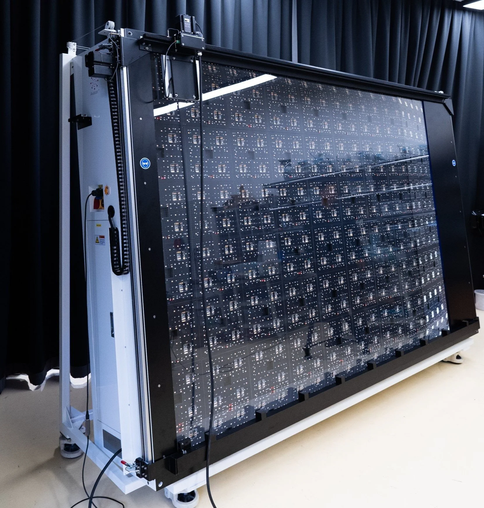 Perovskite and siliconNexun PROA++ A+ A++
Certification-grade silicon with 17 wavelengths, and perovskite tandems with the steady-state add-on.
See the system PRO or PRO Max with the steady-state add-onNexun PerovskiteA+ A+ A+
The two sources in one machine: the premium pulse for the measurement and the 300 to 1000 nm steady-state source for the preconditioning, synced.
See the systemStep by step
The full method in our guide
How to measure a perovskite-silicon tandem, from the EQE of each junction to the stabilised power, with the checks at every step.
Questions we are often asked
Why can't I correct a tandem with one spectral mismatch factor?
Because each junction has its own mismatch, and the current of a two-terminal tandem is set by the weaker one. If the spectrum favours one junction, the other limits and the fill factor changes too. The spectrum has to be adjusted per junction before the measurement (IEC 60904-1-1).
What is a component reference cell?
A reference cell whose spectral response matches one junction of the tandem, for example a perovskite cell or a filtered silicon cell for the top cell and a filtered silicon cell for the bottom cell. Calibrated for its AM1.5G current, it tells you when that junction gets the right light.
How long should a perovskite be preconditioned?
Until its output stops changing, which depends on the device. A drift criterion under maximum power point tracking is more reliable than a fixed time, and the preconditioning should be reported with the result.
Which Nexun do I need for perovskite tandems?
A Nexun PRO or PRO Max with the steady-state add-on. The PRO Max adds per-wavelength on/off, EQE and multi-junction capability for the band tuning.
Rather we contact you?
Leave your email and we will get back to you. No form to fill in.
Measure the tandem you made, not the one the light made.
Tell us your device size, junctions and protocol, and we will configure the bench around them.