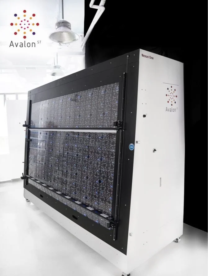
 Electroluminescence Imaging
Measuring a perovskite-silicon tandem means solving two problems together. The perovskite is metastable: ions move under light and voltage, so the result depends on what happened in the seconds to minutes before the sweep. And a two-terminal tandem carries one current through both junctions, so whichever junction gets less of its light sets the current. Get either wrong and the efficiency is wrong, sometimes by several percent.
Why one spectral mismatch factor is not enough
For a single-junction cell, a spectral mismatch factor (IEC 60904-7) corrects the measured current for the difference between the simulator and the AM1.5G reference spectrum (IEC 60904-3). A tandem has one mismatch per junction, and the limiting junction can change with the spectrum. A spectrum that is slightly blue-rich makes the silicon bottom cell limit; a slightly red-rich one makes the perovskite limit. The fill factor moves with it. That is why IEC 60904-1-1 adjusts the spectrum per junction before the measurement instead of correcting after it.
Step 1: measure the EQE of each junction
The spectral response of each junction (IEC 60904-8-1) tells you which wavelengths it uses. On a tandem the junction under test is isolated with light bias that saturates the other junction, and a voltage bias that puts it near short circuit. From each EQE you calculate the current that junction would generate under AM1.5G. On the Nexun PRO Max, the per-wavelength LED engine measures EQE on the same bench as the I-V.
Step 2: one reference cell per junction
Each junction needs a reference whose spectral response matches it: a component (isotype) cell made like the junction, or a filtered cell. Each reference is calibrated for its current under AM1.5G, with traceability to a calibration laboratory. These are the sensors the light is tuned against, so their calibration enters the uncertainty of the final result.
Step 3: tune the LED bands
With the references in place, the light in each band is adjusted until every reference reads its target current at the same time. With per-wavelength LED control this is a software setting rather than a filter change: each band group is flashed, the response of every reference cell is recorded, the levels that put each junction on target are solved, and a confirmation flash checks the result. The PRO Max switches every wavelength on and off and sets its level independently.
- Perovskite top cell: mostly the visible bands, roughly 300 to 750 nm depending on the bandgap.
- Silicon bottom cell: mostly the red and near-infrared bands, roughly 750 to 1200 nm.
- The overlap region decides the balance, so tune with both references read on the same flash.
Step 4: precondition under steady-state light
Bring the device to its stabilised state under continuous light before measuring. The steady-state add-on of the Nexun Perovskite runs a second LED source from 300 to 1000 nm (1200 nm option), with the device held at maximum power point or open circuit. Stop when the output has stopped drifting over a set window, rather than after a fixed time, and log the light level, duration, bias and temperature.
Step 5: measure, and report the stabilised power
On the Nexun the 500 ms pulse fires while the steady-state source is still on, so the device is measured in the state it was brought to. Record forward and reverse sweeps if they differ. For strongly metastable devices, also report the stabilised power from maximum power point tracking, the steady-state method described in IEC TR 63228, next to the I-V result. Stability over hours and days follows the ISOS procedures for perovskites (Khenkin et al., Nature Energy, 2020).
What a tandem result should state
- The preconditioning: light level, duration, bias and stabilisation criterion.
- The reference cells used for each junction and the current each read.
- Scan direction and speed, with both curves when they differ.
- The stabilised power from maximum power point tracking.
- Device temperature during the soak and the measurement.
The whole method on one instrument: Perovskite tandem testing.
Frequently asked questions
- Can I measure a tandem with a standard AM1.5G simulator and a mismatch correction?
- Not reliably. Each junction has its own mismatch and the current of a two-terminal tandem is set by the weaker one, so the spectrum must be adjusted per junction before the measurement, as IEC 60904-1-1 describes.
- Which standards apply to perovskite tandem measurement?
- IEC 60904-1-1 for the I-V of multi-junction devices, IEC 60904-8-1 for the spectral response of each junction, IEC TR 63228 for metastable perovskite devices and the steady-state maximum power method, IEC 60904-3 and 60904-7 for the reference spectrum and mismatch, and the ISOS procedures for stability.
- How long should I precondition a perovskite before measuring?
- Until the output stops drifting under maximum power point tracking, which depends on the device. A drift criterion is more reliable than a fixed time, and it should be reported with the result.
- Which Avalon simulator measures perovskite-silicon tandems?
- A Nexun PRO or PRO Max with the steady-state add-on (the Nexun Perovskite). The PRO Max adds per-wavelength on/off, EQE and multi-junction capability for tuning the bands per junction.